|
Viewing Results |
  
|
|
Viewing Results |
|
In the Results tab you may:
| 1) | View, save and print tabular results. |
| 2) | Perform computations on different coordinate axes. |
| 3) | Perform section analysis with different load cases. |
| 4) | View and print graphical results. |
Result windows are displayed and new menus are available.

Numerical results are displayed in the left portion of the screen under three tabs: Axes Properties, Custom and General.
| 1) | The General tab contains general section properties. |
| 2) | The Axes Properties tab contains section properties with respect to the four standard coordinate systems. |
| 3) | The Custom tab contains section properties with respect to a user-defined position. |
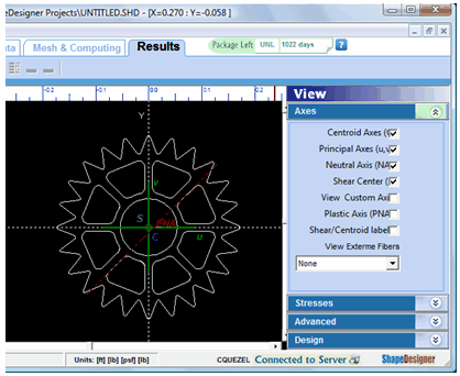
Graphical results selected from the View Toolbox are displayed in the View Area
Changing Number Format
From the Option menu select the Number Format… option.

The General Tab
The General tab contains various section properties, calculated values and the loads applied to obtain these values.

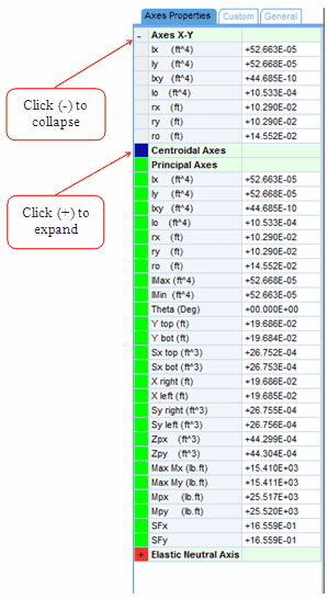
The Axes Properties Tab
The Axes Properties tab contains section properties with respect to the four standard coordinate systems:
|
|
Each category may be collapsed (-) or expanded (+).
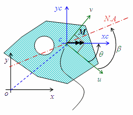
To view a graphical representation of the four coordinate systems, in the View Toolbox, select the Axes tab. Check the required axes and they will be displayed in the Axis View in the View Area.
| 1) | The centroid is a small blue circle identified by the letter C. |
| 2) | The principal axes are shown in green and identified by the letters u and v. |
| 3) | The elastic neutral axis (ENA) is shown in red. |
| 4) | The shear center is small gray circle identified by the letter S. Its x and y distance from the centroid is displayed if the “Shear/Centroid label” is checked. |
| 5) | The plastic neutral axis (PNA) is shown in turquoise. (Not shown here) |
| 6) | The custom axes are shown in purple and identified by the letters XA and YA (not shown here. see the “Custom tab” section) |
The “View Extreme Fibers” highlights the position that is the most distant from the selected axes system (principal, centroid, neutral).
The Custom Tab
The Custom tab is used to compute section properties with respect to a user defined point (A).

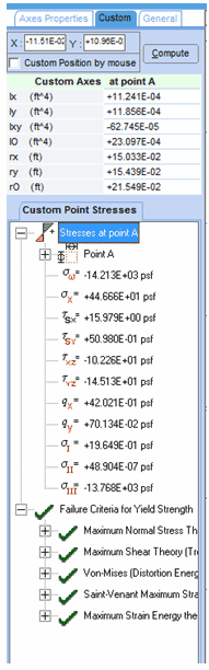
Performing Computations on Different Coordinate Axes
You may compute section properties with respect to a user-defined point (A). To do this, enter the X and Y value of the point’s position and press the Compute button. Another way of selecting the point’s position is to check the Custom position by Mouse checkbox and click on the position in the view area. Clicking on the mouse automatically sets the X and Y values and applies the Compute button. If the View Custom Axes of the Axes tab of the View Toolbox checkbox is checked, the custom axes are displayed in purple in the view area.
The custom axes properties are updated automatically. If the selected point “A” falls inside the section, the Custom Point Stresses values are also updated.
The Failure Criteria for Yield Strength tree evaluates various criteria at point “A” and displays a green check if the criterion is satisfied or a red X is otherwise.
Some of the properties are also displayed in the status bar.
![]()
Viewing Stress Distributions
Using the Stresses tab of the View Toolbox, you may view a graphical representation of the Axial, X-Shear and Y-Shear stress distribution and of the X and Y shear flow distribution. Other graphical results are available in the Advanced tab.
To view one of the three stress distributions, select the corresponding checkbox then, in the view area, press and keep the mouse button down. The distribution axis will be displayed. Move the mouse to position the distribution axis and release the button when it is at the correct position.
Perform the same operations to view the two shear flows. In this case, the position of the distribution axis does not influence the results displayed..

Viewing Maximum Stresses
In the Max/Min Stress tab of the Stresses tab, the minimum and maximum stresses and position is displayed. Expand the tree node to see the position.

Viewing Stress or Shear Flow at a Specific position
To view stress or shear flow at a specific position, select the Selected Stresses tab and right click in the view area.
Viewing various Stresses as Iso-Colors
From the Advanced tab of the View Toolbox, Select the Stress distribution to display. The following 16 options are available:
| 1) | Bending |
| 2) | Warping |
| 7) | Tau Max |

Saving Tabular Results
The data contained in the Results tab may be saved to disk using the Results menu’s Save Tabular Result to ASCII file option. This saves the data as a simple ASCII file using the name of the section project and the .out extension as filename. The file is overwritten without warning.
Printing results
To generate a PDF report, in the Results tab, in the results menu select the Print Graphical Results… option. The following dialog is displayed for you to select the content of the PDF report.

The Print Drawing Section Geometry option will print the content of the view area as displayed when the Axis tab of the View toolbox is selected. Select the elements (centroid, principal axes…) you want to appear in the printed report (see “The Axes Properties Tab” section above) from the Axis tab before printing.
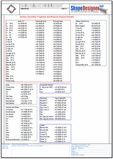
The Print Calculated Geometric Properties option will print the numerical results of the section properties.
The Print Isovalues Axial and Equivalent Stresses and Print Isovalues Shear Stresses option will print a printer friendly representation of the specified stresses.
The following pages show a typical report.