|
Setting the Project Preference |
  
|
|
Setting the Project Preference |
|
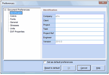
The Preferences dialog is used to set various project specific properties. This dialog may be invoked at anytime from the Options menu by selecting the Preferences … option or by clicking on the Preferences icon on the main toolbar. This dialog is automatically displayed when starting a new project.
Properties are grouped in categories displayed as tree nodes on the left side of the dialog. For example, the “identification” node groups all properties related to project identification. The property values are displayed on the right side of the dialog.
The Set as default preferences checkbox saves the values of all properties of all categories (not just the currently displayed values) as default values to be used whenever a new project is started. The Reset to default button restores values of all properties of all categories to the last saved values (not to the original system values). The Ok button applies the changes made to all properties of all categories. The Cancel button reverts to the values set before the dialog was invoked.
For most of the categories, you may accept the default property values. The two categories you may want to change are “Identification” and “Units”.
The Identification category contains the project identification information. The “Company” property is read only and is set by your administrator using the web interface. The “Version” property is also read-only and corresponds to the software version number. These properties are displayed in the various generated reports. The “Client”, “Project”, “Task” and “Project Ref” properties differ from all other properties in that they are not saved when the “Set as default preferences” checkbox is checked.
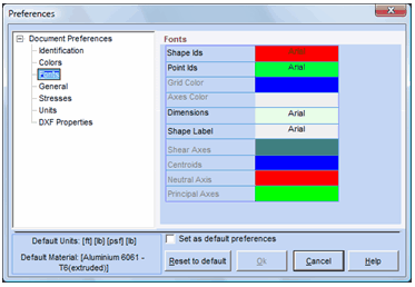
The Color category is used to set the color of various display elements. The current color is shown to the right of the element. Clicking on the current color activates the Color dialog to help you select a new value.

The Font category is used to set the font of various display elements. The current font is shown to the right of the element. Clicking on the current font activates the Font dialog to help you select a new value.
The General category is used to set various general-purpose properties. These properties are grouped under two tabs: “Mesh & FEA Parameters” and “Sketch Parameters”.

Mesh & FEA Parameters: (FEA stands for Finite Element Analysis)
| a) | AutoCompute Properties: When checked, ShapeDesigner™ automatically meshes the geometry with an optimal density in the “Mesh & Computing” tab. When left unchecked, you must select the mesh density explicitly, mesh the geometry and review the mesh before moving to the computation phase. This checkbox is also displayed in the “Mesh & Computing” tab. |
| b) | Point inside shape ratio: This value is used to define a relative tolerance used to detect shapes and holes. The default value of 1000 means that the tolerance is 1/1000 of the maximum X and Y dimension. You should rarely, if ever, have to modify this value. In some very rare cases involving multiple shapes or holes with very thin walls in contact with each other, the meshing process may fail. You should first make sure the geometry is correct as this is almost always the real problem. As a last resort, try to increase this value by a factor of 10 or 100. |
| c) | Tolerance to link shapes (FEA): When multiple shapes are assembled to form a built-up section, a tolerance value is used to determine if the shapes should be “linked” together. When a node from a shape is closer than this tolerance value to another shape, the node will be “linked” to this shape. Depending on the problem being solved, you may want to |
| a. | Move certain shapes to make sure they fall inside or outside this tolerance value, |
| b. | Change the tolerance value; or |
| c. | Both |
The second group of properties under the General category is the “Sketch Parameters”.

Sketch Parameters:
| a) | Number of divisions per circle: Circles are approximated by line segments. This value determines how many such segments are to be used for this approximation. The default value of 80 is generally Ok for most problems and should not be changed. |
| b) | Grids spacing ticks: |
| c) | Snap mouse to nodes: |
| d) | Snap mouse to nodes (pixel): maximum value between mouse and node to snap it. |
| e) | Step to move shape in X direction: step in pixel to move shape with left-right arrow key. |
| f) | Step to move shape in Y direction: step in pixel to move shape with up-down arrow key. |
| g) | Auto Bounding box: When checked, ShapeDesigner™ automatically resizes the bounding box to include exactly all the current shapes. See “Setting the Bounding Box” section for more details. |
The Stresses category is used to specify the number of divisions when viewing results. This value is “Not” the number of iso-colors. This value affects the rendering of stresses as displayed in the Stresses tab of the View toolbox of the Result tab.

The Units category is used to specify the units and the numerical display format used by ShapeDesigner™. Double click on the units and the Change Units dialog will be displayed. See the “Setting Section Project Units” section below for more details. Select the display format for floating point values using the “Number Format” dropdown list.

The DXF Properties category is used to specify the parameters when importing DXF files in ShapeDesigner™.
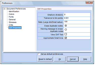
Small arc divisions: W
Tolerance to link points: W
Ration (Large dim/Small radius): W
Erase duplicate nodes:
Warning message to erase duplicate nodes: W
View DXF Text: By default, when showing DXF files, ShapeDesigner™ does not show the contained text. In some cases, it may be useful to display this text and this option allows you to do this. Note that this option is also available in the “DXF File Manager” of the “DXF Module” tab.
Approximate Small Arcs:
Setting the Section Project Units
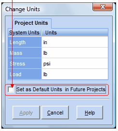
The Change Units dialog is used to select the units to be used by ShapeDesigner™ for all future operations. The Change Units dialog may be invoked at any time by:
| 1) | Clicking the Change Units icon on the toolbar |
| 2) | From the Options menu by clicking Change Units … option. |
| 3) | From the Preferences dialog in the units category. |
The Change Units dialog is automatically displayed when starting a new project if you have not previously checked the “Set as Default Units for Future Projects”. Note that changing units actually performs unit conversions when shapes are loaded. For example, a 1-inch edge becomes a 2.54 cm edge. Click the Apply button when you are done.
You can use the selected units in the future projects by selecting on the
“Set as Default Units for Future Projects” checkbox.
The “bounding box limit” and the “auto bounding box checkbox”, in conjunction with the zoom buttons, control which portion of the drawing is displayed in the drawing area. The bounding box is an imaginary box that surrounds a region of the drawing. Zooming operations are based on the size and position of the bounding box. For example, the Zoom All command resizes and moves the viewport so that the bounding box is centered and fully visible in the drawing area. After the Zoom All command is executed, the Zoom dropdown is set to 100%.
The bounding box limit is defined by setting the minimum and a maximum X and Y value to be displayed in the drawing area. There are two methods of setting this limit:
| 1) | Manually specifying explicit values in the Bounding Box Boundary dialog. |
| 2) | Using the mouse pointer to select a region in the drawing area. |
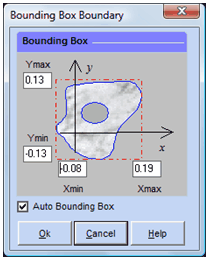
To set the limit, from the Options menu select the Change Bounding Box option and then select one of the two methods described above. When you select the Manually… option, the Bounding Box Boundary dialog is displayed to set the limit values. When you select the Mouse option, the mouse pointer changes to a horizontal cross and you can then select the part of the drawing area to use as the limit.
By default, ShapeDesigner™ automatically resizes the bounding box to include exactly all the current shapes. When a shape manipulation causes a shape to exceed the bounding box limit or to be smaller than this limit, the bounding box will be resized. This default behavior may be counter productive when the user is trying to concentrate on a particular region of a drawing. The Auto Bounding Box checkbox, located in the Bounding Box Boundary dialog and in the Preferences dialog, in the General properties, under the Sketch Parameters tab, is used to turn off automatic resize.