|
Creating Shapes |
  
|
|
Creating Shapes |
|
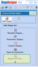
Assembling shapes with holes creates sections. To specify whether a shape or a hole is to be inserted in the drawing area, from the Main Toolbox under the Cross Section Input tab, click the Add Shape or the Add Hole toggle button. Because holes can only be added to shapes, the Add Hole toggle button is not accessible if a shape is not selected.

Pressing the Add Shape or Add Hole toggle button activates the list of shape definition modes. Select one of the five shape definition modes.
| 1) | Standard Shapes… Inserts standard steel sections from a library of all standard AISC (American Institute of Steel Construction), CICS (Canadian Institute of Steel Construction) and BS (British Standards) sections. |
| 2) | Parametric Shapes… Inserts predefined parametric shapes from a library containing all common sections such as Multi-Stiffeners, (including all AISC shapes). |
| 3) | Custom Shapes… Creates user-defined shapes using one of the following methods: |
| a. | Freehand using the mouse pointer. |
| b. | Using data from a text data input file. |
| c. | Using complex mathematical functions. |
| 4) | Input by Keyboard… Creates user-defined shapes using a Microsoft Excel like table of X and Y coordinates. |
| 5) | Import DXF file… Imports a DXF format file to ShapeDesigner™. |
Guidelines for Creating Shapes
The method used to create shapes and the number of shapes required is specific to the problem being solved. The following guidelines should be followed.
| 1) | ShapeDesigner™ assigns material properties to shapes. If you plan to use various materials, you will need at least one shape per material type. |
| 2) | ShapeDesigner™ automatically links (glues) together common shape boundaries. To detect common shape boundaries, the distance between two boundaries is compared to a very small tolerance value specified in the Options/Preferences/General/Mesh & FEA Parameters/ Tolerance to Link Shapes property. If this distance is smaller than the tolerance value, the boundaries are assumed to be linked. Users should be very precise when assigning point coordinates. |
Creating Shapes by Importing DXF Files
Select the Import DXF File… option or click on the DXF Module tab to import DXF files in ShapeDesigner™ or from the File menu select the Import/Export Import Section from DXF file option. Use this option when you want to import a shape that was defined in another CAD. ShapeDesigner™ reads DXF files and provides functions for extracting and cleaning data before it is imported. The DXF file can be a collection of polylines, lines, arcs and circles.
How Should a DXF be Formed?
ShapeDesigner™ expects a DXF to represent a series of shapes and holes drawn as a closed list of graphical elements such as lines, arcs … How a DXF is created, influences how easily it can be imported in ShapeDesigner™. A DXF can be a simple well structured closed polyline (which, by the way, may be made up of graphical elements other than lines) or an unordered set of thousands of lines, arcs, circles … A DXF polyline is easily imported because it already encompasses the structure and ordering required. On the other hand, when given an unordered set of lines, arcs, circles …, ShapeDesigner™ must discover the shapes and holes by finding which elements follow each other and in what order. This process may need user intervention in some cases.
Step-by-Step Import of a DXF File
1. Go to the DXF File Manager by clicking on the DXF Module tab or by selecting the Add Shape | Import DXF File… option in the Cross Section Input tab of the Drawing & Data. Note that by switching to the DXF Module tab, menu options are changed. For example the File |
Open Project... option is not available anymore. If the DXF Editor is displayed, from the main menu select File | Open DXF File...
2. Select the folder where the DXF file resides in the folder tree.
3. Select the DXF file from the file list. The selected DXF file is previewed in the drawing area.
4. Some strangely formed DXF files contain drawing elements in blocks. If your DXF is missing information, check the Load Block option. This option is off by default but is turned on automatically if nothing is found in the DXF.
5. Check the View DXF Text checkbox to view textual information in your DXF that is typically not required when importing sections.

6. If the DXF file contains unwanted information for section analysis, you can pre select a specific part of the DXF for the DXF Editor using the mouse pointer in the drawing area. Completion of the mouse selection automatically accepts the DXF file with the pre selection and goes directly to the DXF Editor. Note that this pre selection step with the mouse pointer is only a shortcut to the DXF Editor which offers the same functionality and more. The DXF Editor section below describes how to perform a finer selection.
7. Click the Accept button to perform a pre selection of the whole DXF file content and go directly to the DXF Editor. The DXF Editor will allow you to refine your selection before the DXF is actually imported in ShapeDesigner™.
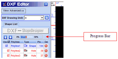
8. The DXF Editor is an intermediate step before importing the DXF file in ShapeDesigner™. If the DXF Editor selection contains only the desired section without unwanted information like other sections, projections …, press the button to import the current selection to ShapeDesigner™.
![]()
During import, the import button is disabled and a progress bar is displayed.
9. Follow the DXF Editor instructions below to finely select part of a DXF file.
The DXF Editor
The DXF Editor is used to select, edit and help import DXF sections in ShapeDesigner™.
Setting the DXF Dimension Unit
A DXF file is unitless when it is created without specifying the dimension unit (mm, inch …). In this case, you can explicitly specify the dimension unit using the “Original DXF Unit” dropdown list. If you forget to set the unit, you will be reminded when you perform the import. It is important to note that the dimension unit you specify is the one used to draw the DXF in the other CAD. If you work with another unit type within ShapeDesigner™, the DXF dimensions will be converted later during import.
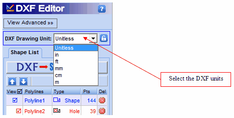
If the dimension unit has been improperly set, you may override its value by clicking on the small lock icon to the right of the “Original DXF Unit” dropdown list. This enables the “Original DXF Unit” dropdown list. Changing this value does not perform a conversion (1 mm will become 1 cm or 1 inch). If you work with another unit type, the DXF dimensions will be converted later during import.
Selecting the DXF Elements
To import shapes and holes from a DXF, you have to select the part of the DXF that contains the information you want to import. For example, if a drawing contains a front, a horizontal and a profile view, you will select the front view for import. If a drawing contains multiple sections, you will import only one of them. To select the DXF elements, click on the Select Item (Shapes) by Mouse icon.

If there was a previous selection, it will be canceled and you will be placed in selection mode. Using the mouse pointer, select the part of the DXF you want to import.
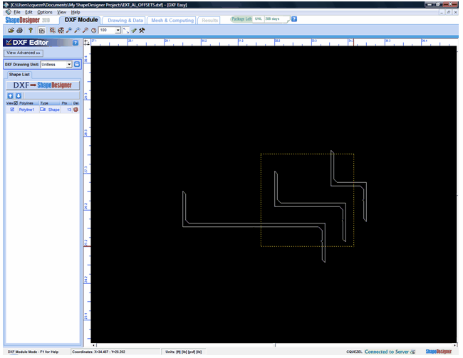
In most cases, ShapeDesigner™ will automatically detect the selected shapes and holes and will display the selected result as shown in the next figure.

If you are satisfied with your selection, click on the DXF to ShapeDesigner™ button and the selected section will be imported in your current project. If you have not captured all the desired shapes, you can start over your selection by clicking again on the Select Item (Shapes) by Mouse icon. If you want to remove unwanted shapes, you can use the fine selection detailed in the next section. If the DXF does not render correctly, you will have to go to Advanced mode to guide the shape selection.
Fine Selection
In the previous example, the shape selection operation was simplified because the DXF was made up of three well formed polylines. When you do not have such a well formed DXF, or when you are not able to select your shapes with the mouse pointer, you may use the Shape List to remove unwanted shapes or the Advanced mode to guide shape selection.
Shape List
The Shape List tab lists all the closed polylines (shapes and holes) that were discovered in the current selection. Shapes are listed in blue while holes are listed in red and indented within the containing shape. ShapeDesigner™ automatically assigns shape or hole type. Because it can’t know for sure if a polyline represents a hole or a shape (with another material), ShapeDesigner™ allows you to change the shape type by clicking on the “type” column.
Polylines may be moved up or down with the arrow keys to ensure holes are contained in the right shape when you change the polyline type. Click on the polyline name to select it then click the arrow buttons.
When the “view” column checkbox is set, the corresponding polyline is displayed and flagged to be imported. Otherwise, the polyline will be hidden and ignored when the DXF is imported. Because holes are contained in Shapes, if a shape is unchecked, all its holes will be unchecked automatically. Clicking on the View column header will select or unselect all polylines.
To reduce cluttering in the shape list, you may delete polylines by clicking on the corresponding “delete” icon on the right size of the list. This will automatically hide the polyline and ignore it when the DXF is imported.


