When creating built-up sections, you have to position shapes relative to each other. To do this, use the Snap Shapes tool. This tool is more flexible than a “snap to grid” feature as, for example, it allows diagonal moving of shapes.
The Snap Shapes tool is invoked by selecting a shape and then:
| 1) | Selecting the Snap Shapes… item from the Shape menu, or |
| 2) | From the Toolbox, under the CAD and Data tab, under the CAD tab, click the Snap Shapes… icon. |
The Snap Shapes tool performs one of three operations:
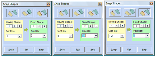
| 1) | It aligns a point on the moving shape to a point on the fixed shape. |
| 2) | It aligns a point on the moving shape to a line on the fixed shape. In this case, the point moves in a direction perpendicular to the destination line. |
| 3) | It aligns a line on the moving shape to a point on the fixed shape. In this case, the line moves in a direction perpendicular to itself. |
The first step is to choose the movement type by selecting one of the three movement buttons at the top of the Snap Shapes dialog. The following images show the three possible cases.
. 
By default, the “Moving Shape” is the one you selected when you invoked the dialog. If it is not already selected, select the shape to move using the horizontal scrollbar in the yellow section. As you scroll through the shapes numbers, the corresponding shape is highlighted using yellow hatching in the drawing area (see screenshot below).
Select the point or side to align on the moving shape using the “point | side ids” dropdown. The selected point or side is highlighted in red in the drawing area.
Repeat the above steps for the fixed shape in the green section. Note that the fixed shape will be highlighted using green hatching in the drawing area.

Once you have entered valid data in the Snap Shapes dialog, the Snap button is enabled. Click on the button to perform the move action.


