|
Meshing and Computing Geometric Properties |
  
|
|
Meshing and Computing Geometric Properties |
|
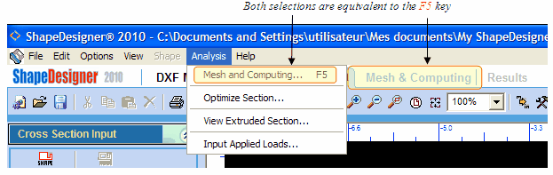
To compute geometric properties, from Analysis menu select the Mesh & Computing… option or click Mesh & Computing.tab or press the F5 key.
ShapeDesigner™ will check the section geometry and give an error message if the geometry is not acceptable for computing geometric properties. Some of the common reasons that may prevent your section from being computed are:
| 1) | A hole extends outside its containing shape. |
| 2) | The section is made up of shapes that are not connected together (see tips to handle this). |
| 3) | A shape contains an invalid boundary. |
| 4) | The area of a shape is zero. |
| 5) | … |
The applied loads will also be checks to ensure the required values are set. Access to the Mesh & Computing Tab. is only granted if the geometry and loads are acceptable.
Changing the Mesh Density
Once the Mesh & Computing Tab is displayed, you can change the mesh density before proceeding to the property computations. If the “Automatic Optimal Calculation” checkbox is set, ShapeDesigner™ will automatically find a good mesh density for your section. This is the preferred method for simple sections. Note that the mesh is used to compute the torsion (J) and warping (Cw) constant only. Other properties do not require a mesh.

 Mesh Section button to view the new mesh. Repeat these two steps until you are satisfied with the mesh density.
To obtain precise values of warping (Cw) and torsion (J) constants, the mesh must be uniformly distributed and have an adequate density.
Linking Common Shape Boundaries Together
Before proceeding to the meshing phase, ShapeDesigner™ eliminates common boundaries by linking them if they fall within a tolerance distance (e).

 The tolerance distance is compared to the distance a between two points (or point and side) from two shapes. If the distance a is less than e the two shapes are linked by merging the two points (or by merging the point and the equivalent position in the adjacent side).
The tolerance distance is specified in the Preference dialog in the General category in the Mesh & FEA Parameters.
Checking Common Boundary Linking
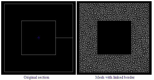
When designing build up sections, it is important to check the generated mesh to ensure that it is continuous over boundaries that should be “linked” and discontinuous over boundaries that should not. For example, in the following example, a section is build from three shapes. The top rectangle falls within the tolerance value while the right rectangle doesn’t. This leads to invalid results as shown on the stress view on the right.

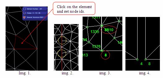
There are a few ways to detect these problems. You can visually detect discontinuities (shapes that are not linked together) along the border by closely examining the mesh.
| 1) | Clicking on an element will display its number, nodes ids and material. If elements on both side of the common boundary have 2 identical nodes, then they are linked. This is shown in image 1 below. |
| 2) | Visually, you may observe discontinuities at the border. This indicates an unlinked border. In image 2 below, which is a zoomed view of the previous mesh, two discontinuities (circled in yellow) are detected along the border (shown in red). |
| 3) | If you display node Ids, as in the image 3 below, and two node Ids appear at the same position, then you have a discontinuity. |
| 4) | If you zoom in on a region and see the two shapes. This is shown in image 4 which is a zoomed view of image 3. |
Linking of common boundaries may occur with a single shape. For example, the following C shape common boundary is merged which is probably not the user’s intent. The results show the differences between a linked and an unlinked border.

The best way to fix a border continuity/discontinuity problem is to:
| 1) | If only one shape is involved, edit the shape and move the border. This is normally done by going to the Drawing and Data tab, selecting the CAD and Data tab in the main toolbox and then selecting the Geometry Edit tab. |
| 2) | If two shapes are involved and you want to link the shape borders, select the shape to move and from the Shape menu, select the Snap Shape… option. |
Printing the Mesh
If you want to print the mesh, from the Mesh menu select the Print… option. The mesh will be printed using the same parameters as those specified in the Mesh & Computing tab. Those parameters are Show/hide axes, Show/hide node ids, Show/hide element Ids, Show/hide material colors.

Computing Properties
When the mesh is correct, click the Compute Section Properties button or from the Compute menu select Compute Section Properties… ShapeDesigner™ computes the properties and when done switches from the Mesh & Computing tab to Results tab.